The first three days after a powder coating machine arrives decide how the unit will behave for years. It leaves the factory as the same set of standard parts, yet every site installs it differently: not enough air, only one grounding point connected, powder hose pulled dead straight, settings kept in one operator’s head. What matters in those three days is not whether the crew finished, but four things: power, air and ground in place; pipe runs done right; readings stable; parameters written down.
1. Day One: Power, Air and Grounding First
If those three are not ready, the installation crew can only stand and wait. The trade has a saying: the equipment is three parts, installation and commissioning are seven. Here is the baseline. Guns run on 220V, budget 50W per gun. Inlet air pressure 6.0kg (0.6MPa) or above, moisture under 2 percent, and the air line kept separate from the booth line. Allow 0.2 m³/min per gun. Drive the ground rod at least 2 metres deep.
Item
On-site baseline
How to verify
If it falls short
Main power
220V, 50W per gun, dedicated circuit
Measure no-load voltage, then measure again with the unit running
Voltage sag, controller alarms, powder feed stutters
Main air
6.0kg or above, moisture under 2 percent, 0.2 m³/min per gun
Read the gauge static, then read it with guns firing
Feed varies, pressure drops when several guns fire
Pipe size
2 inch main on horizontal lines, 3 inch to the cabinet on vertical lines
Measure main and branch connections
Low pressure at the far end, weak feed on distant guns
Grounding
Rod 2 m or deeper, three connection points
Ground resistance meter
Poor deposition, powder will not hold on the part
The three connection points are: controller earth to the ground rod, lift earth to the ground rod, and the rail expansion nut to the controller earth. Photograph all three on the day; you will not want to climb the frame again when a grounding question comes up later. On dry gravel, move the rod or go deeper rather than settling for a short one.
2. Siting the Cabinet and Gun Rack
Where the gun cabinet and controller sit is not a matter of finding empty floor. From the operator position you should see the parts inside the booth; the cabinet doors must open fully with service space behind; keep the cabinet out of the direct return-air path, because powder build-up inside affects board cooling and terminal contact; and run the powder hose from the feed centre to the gun rack as short and as straight as possible.
Move the controller in on its trolley and drive the ground rod before connecting external components. Check the compressed-air hose for bend radius as well as length: a sharp bend chokes flow at the elbow, which shows up as feed coming in bursts. Cap unused ports with blind plates. An open port takes in powder and moisture and is a common starting point for spitting later on.
3. Day Two: Piping and Numbering
Installation work falls into four groups: the controller (earth, mains, signal cable, air inlet), the powder pumps and their red and black air tubes, the gun cables and powder hoses, and the main air supply. Two requirements are not negotiable. The arrow on the main air pump must point inward, or the air circuit cannot move powder. And the pump, gun cable and powder hose numbering must match one to one, marked with a pen at both ends.
Component
Marking at one end
Marking at the other end
What happens without it
Powder pump
Controller outlet number
Pump number
Crossed pumps, feed rate does not match
Red/black air tube
Controller port number
Pump port number
Reversed tubes, pump does not cycle
Gun cable
Controller gun number
Gun body number
You adjust the wrong gun
Powder hose
Pump number
Gun number
Lengths and routes mixed up at replacement time
On a multi-gun setup such as the V12 automatic gun, one number out of place shows up as “that one gun will not adjust”, and it takes an hour to find the crossed cable. One more rule on routing: never clamp down the powder hose or air tube, and leave a bend radius at every turn. A flattened hose removes a slice of feed output, while the crew usually suspects pump wear first.
4. Day Three Morning: Dry Run Before Powder
Do not load powder as soon as the wiring is done. Run dry first: power the controller and watch the display, trigger the gun and listen for the solenoid, read the air gauge static, then check voltage at the gun tip. Only when those three readings are steady should powder go in.
Unstable air pressure is the usual problem in this half day. There are four common causes; check them in this order rather than stripping the gun:
Symptom
Check first
How to confirm
Feed rate swings
Compressor capacity
Fire several guns together, watch the gauge drop
Single gun fine, several guns drop
Too many draw-off points, undersized pipe
Add up gun demand against compressor output
Gauge needle trembles or pressure creeps down
Receiver tank volume, blocked oil-water separator, leaking pipe
Watch how fast pressure recovers after guns stop; soapy water on joints
Controller shows output, no powder
Compressed air not connected, or powder path blocked
Feel for air at the hose first, then clean the nozzle
Powder flows but will not deposit
Part or hanger not grounded
Measure hanger to ground rod with a resistance meter
The manual for the E7 manual gun lists these two at the top of its troubleshooting table: controller powered but no powder means check for compressed air first; powder flows but does not wrap means check part grounding first. Getting the order right saves half the teardown time.
5. Day Three Afternoon: Test Spray the First Part
The point of the test spray is not a handsome sample. It is a set of settings you can use again. Same powder, same batch of parts, and the next shift can dial it back in — that is what finished commissioning means.
Record
Starting point
Why it matters
Powder type and batch
Per part specification
A new batch changes deposition, so settings move with it
Voltage setting
Start low, raise while watching pattern and coverage
Too high bounces off, too low will not hold
Feed rate setting
Small first, watch film build
Feed rate is the main driver of film thickness
Atomising air
Increase until the pattern opens
Too much scatters powder, too little gives slugs
Gun distance
Fix one value inside the 200–300mm range
Change the distance and film thickness changes with it
Line speed or stroke speed
Set by takt, record during the trial
Directly tied to film thickness
Ambient temperature and humidity
Read from the shop meter
High humidity reduces powder flowability
200–300mm is the customary adjustment range in the trade. Where you land inside it depends on the part: flat panels can sit further out, recessed parts need a shorter distance and tighter atomising. Judge the pattern in three places — centre, edge, and the internal corner on the part. If all three hold powder, the setup is done. Number the sample, photograph both sides, and staple it to the parameter sheet.
6. Four Things Missed in the First Three Days
Earth connected at the controller only, with the rail and lift left out. Parts hang on the rail; an ungrounded rail means an ungrounded part, and the symptom is “the gun is fine but coverage is poor”.
Air line shared with the booth. Every booth movement changes pressure and the guns feed unevenly.
Powder hose cut to a straight line and pulled tight on installation. Leave a bend radius and you have slack for gun changes and colour changes.
Parameters kept in someone’s head. Change the shift, the operator or the powder, and one machine produces three different results.
Checklist
Power, air and grounding confirmed before the crew arrived, photos filed
Static air pressure at 6.0kg or above, acceptable drop with several guns firing
Air moisture under 2 percent, oil-water separator draining normally
All three earths connected: controller, lift, rail
Pump, gun cable and powder hose numbering matches at both ends
No crushed hose or tube, bend radius left at every turn
Dry run steady: display, solenoid action, air gauge
Parameter sheet filled in and taped inside the cabinet door
The first three days install piping, but they also set habits. Send us your part photos, dimensions, daily output and site power and air conditions, and we will walk through the checkpoints in this order with you. If it helps, start with a sample spray and let measured results decide the configuration. Contact us.
Related Equipment
Models commonly used in this situation — tell us your workpiece and we confirm the fit:
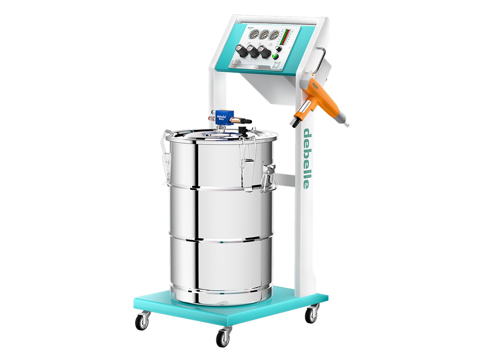
DEBELLE's classic entry-level manual electrostatic powder coating gun with adjustable 0-85kV output and automatic voltage tracking by gun distance. A cost-effective choice for flat panels and small-to-medium batches.
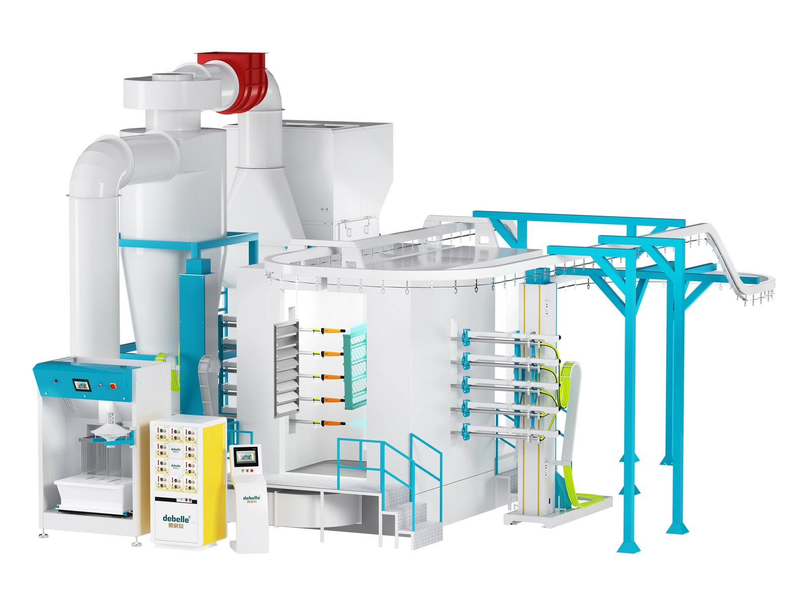
Automatic version sharing the same control unit as the E7 manual gun, ideal for conveyor-line batch coating with a reciprocator. Control unit is reusable, keeping upgrade costs low.
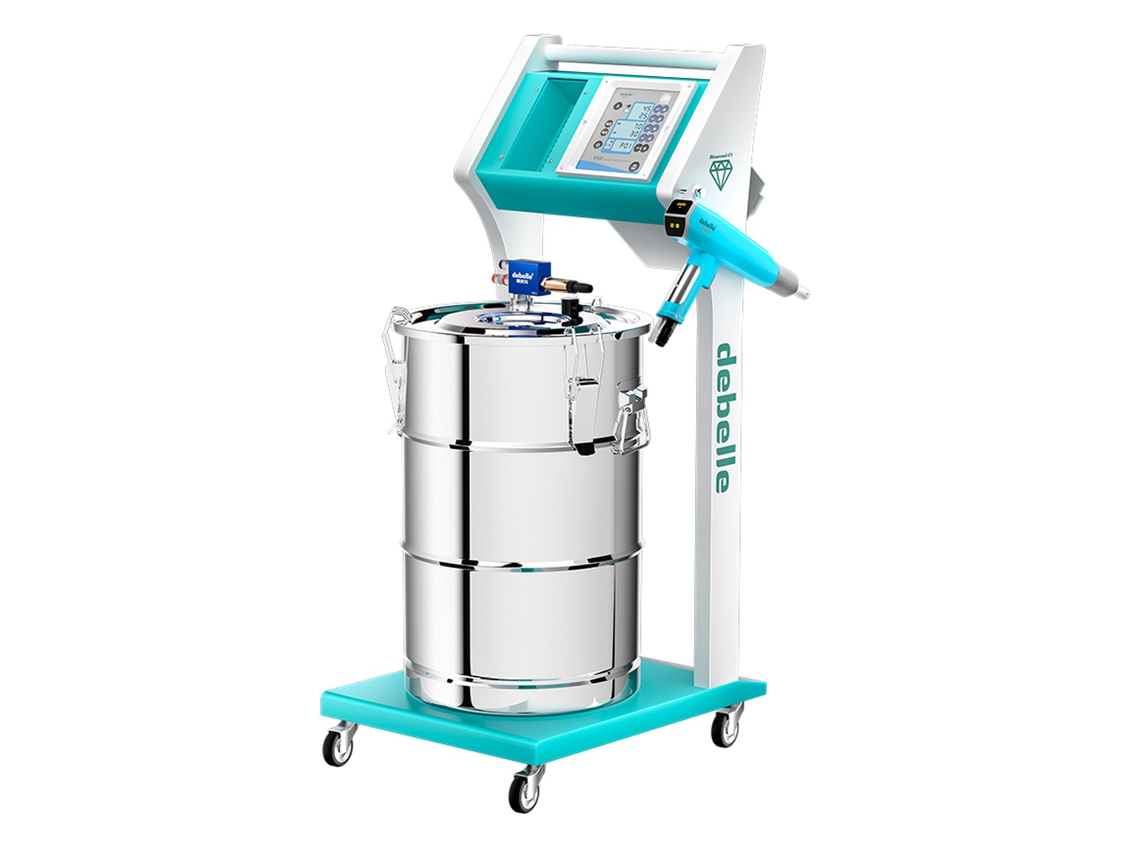
The all-round CNC machine, all in one step: 0-100kV with LCD display, 20 main programs + over 500 sub-programs storage, one-touch gun purge — covering all the capabilities of the E7 and 960.
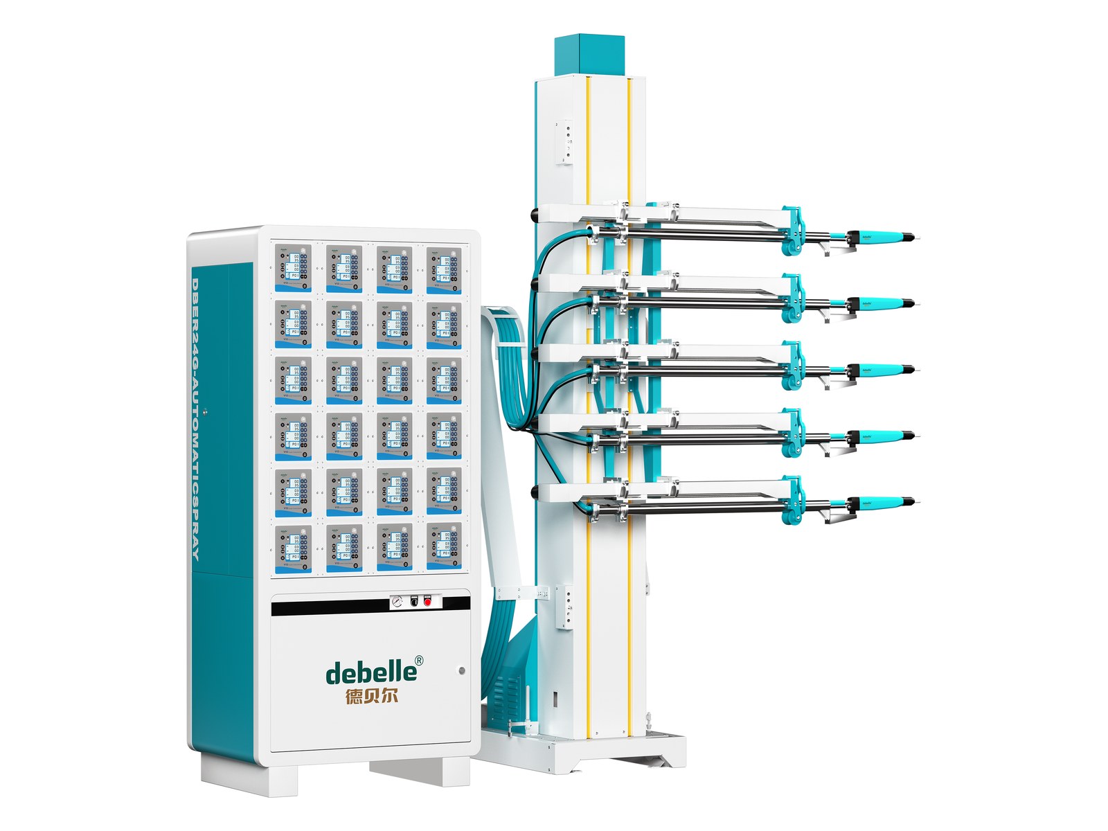
CNC automatic flagship with one-touch gun purge, multi-gun interlock control, and cross-backup control units that keep production running — the core solution for large powder booth automatic lines.
View details →
Need a Proposal for Your Workpieces?
Provide workpiece dimensions, material and daily output — we deliver selection advice and a configuration list.