The same powder coating gun holds up fine on a flat-panel line and then sprays unevenly the moment you switch to deep recessed parts. On a single-color, high-volume line it runs all day; on small batches with frequent color changes it stops for cleaning constantly. The gun is rarely the problem. The mismatch between working condition and configuration is. Pick in this order: define the condition, then the gun direction, then the parts list.
1. Decide which band your shop belongs to
Do not judge by shop size. Judge by four variables: part geometry, hanging density, color-change frequency, line takt.
| Variable |
Case A: high-volume flat parts |
Case B: complex and recessed parts |
Case C: small batches, many colors |
| Part geometry |
Flat, straight tube, simple bends |
Recesses, deep cavities, mesh, odd shapes |
Mixed, often prototypes |
| Hanging density |
Dense, continuous |
Medium-low, needs spray space |
Low, single piece or small rack |
| Color changes |
One color a day or less |
A few colors a week |
Several a day |
| Line takt |
Continuous, fast |
Intermittent, controllable |
Irregular, job-driven |
| Main constraint |
Output stability and takt |
Coverage in dead corners |
Color-change speed and powder-path cleaning |
If the four variables fall in the same column, configure for that band. When they cross bands, for example flat parts with frequent color changes, let the main-constraint row decide the core configuration and add the other band’s requirements on top.
2. Case A: high-volume flat and simple parts
The pain here is output drift: the gun looks fine, yet film thickness wanders over the day. The point of the configuration is to lock parameters down and keep manual intervention low.
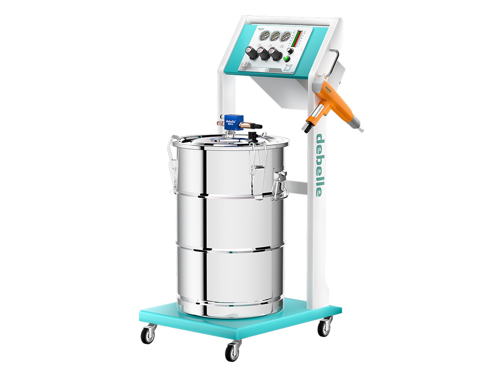
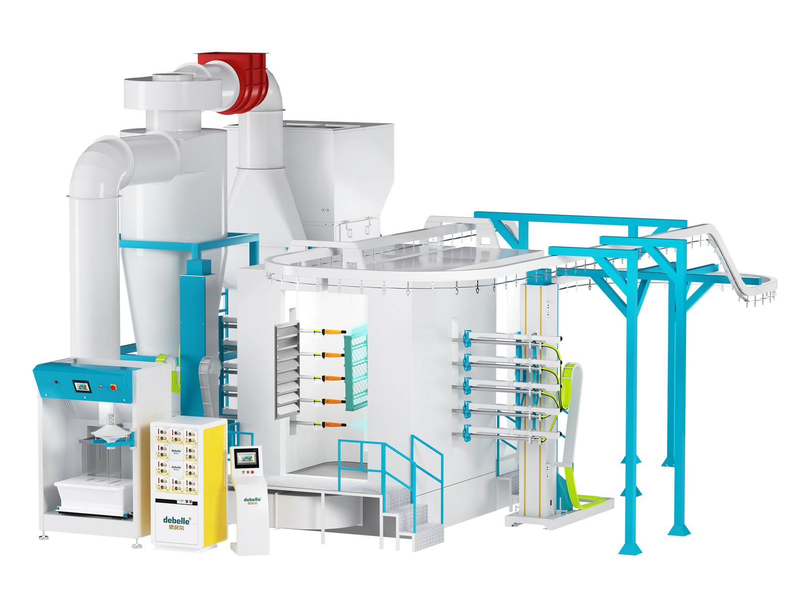
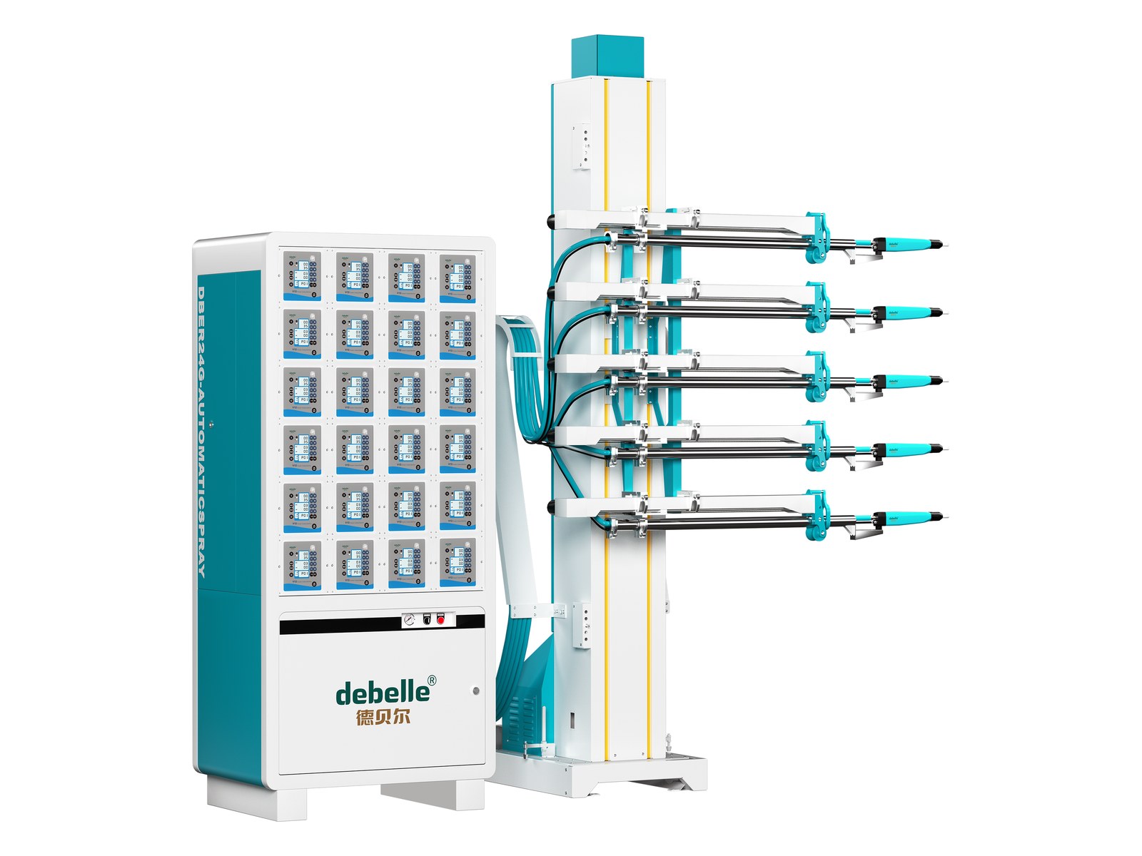
Direction: automatic guns with a reciprocator or fixed gun positions. Prefer a control unit that stores parameters, so a proven setup is recalled instead of re-found every shift. For manual work, a pressure-regulator entry model keeps the setup simple and easy to service on site.
- Voltage and current: start flat parts at 70–90 kV and 40–60 μA, then narrow the range from measured film thickness.
- Powder output: up to 500 g/min under test conditions. On a real line, stay inside the band that matches the part and hanging density; there is no need to run wide open.
- Powder hose: for higher output, use the 12×17 mm option, which balances flow and atomization.
- Air supply: fix pressure stability first. An undersized compressor, a small receiver tank, too many take-off points or leaking pipework all make output surge and dip during spraying.
3. Case B: complex shapes and deep recesses
Recesses and deep cavities usually fail for a different reason: like charges repel. The powder is already charged, so it bounces off the recess wall instead of settling. The configuration priority here is to reach the surface and reduce the repulsion.
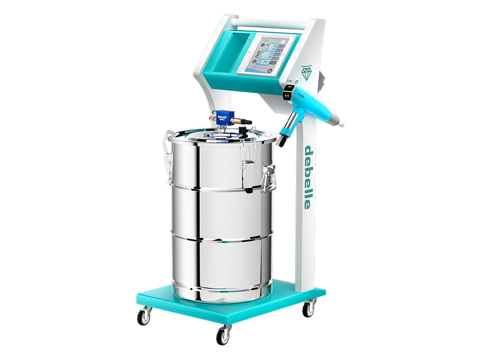
Direction: a higher degree of automation is not automatically the answer. For recessed parts, pick a model with fine voltage and current adjustment and per-part parameter storage. For local deep cavities, use a manual gun with an extension bar.
- Voltage and current: start recessed parts at 60–80 kV and 30–50 μA, one step below flat parts, to cut rebound. Drop to 20–40 kV for recoating.
- Nozzles and extensions: round nozzles come in 15 / 18 / 21 sizes plus extra-small and extra-large; flat-fan openings come in 2.0 / 3.0 / 4.0. For deep cavities, reach in with an extension bar, with 200 / 300 / 500 mm the common lengths and custom lengths available.
- Powder hose: where even atomization matters, use the 11×16 mm option, common for aluminium, lighting and coil-coated parts.
- Reuse parameters: the V12 automatic gun stores parameters per part, so you recall them when the part changes. For manual work, this class of setup is covered by the E7 manual powder coating gun.
4. Case C: small batches and prototypes with many colors
Here the cost is not powder. It is downtime. Change color three times a day and cleaning time per change decides the day’s output. The configuration focus shifts from spraying performance to cleaning speed.
Direction: a manual gun or a small automatic setup, and prefer a model with one-touch gun cleaning, which blows residual powder out of the pump, hose and gun in one pass instead of brushing it out piece by piece.
- Keep the powder path short: the shorter the hose, the faster it cleans, and prototype work does not need a long run.
- Venturi and air-injector nozzle: with frequent color changes, powder build-up on the injector disturbs the airflow, the Venturi wears unevenly and output stops being consistent. Make injector cleaning a fixed step of every color change instead of waiting for a symptom.
- Voltage and current: set them per powder type for that run, for example 60–80 kV for metallic powders and 50–70 kV for texture powders. One setting does not cover every color.
5. Parameters follow the part and the powder, not the gun
Change the part or the color and the settings change with it. The table below gives starting bands for common combinations; narrow them on site against measured film thickness and appearance.
| Part and powder |
Voltage range |
Current range |
| Flat part / smooth powder |
70–90 kV |
40–60 μA |
| Recessed part |
60–80 kV |
30–50 μA |
| Metallic powder |
60–80 kV |
30–50 μA |
| Texture powder |
50–70 kV |
10–30 μA |
| Recoat |
20–40 kV |
10–30 μA |
The unit adjusts voltage from 0 to 100 kV and current from 0 to 100 μA, so every band in the table sits inside the range. These are conventional starting points. The run’s film thickness and appearance decide the final setting. Two operators on the same numbers will not land in the same place, which is exactly why the settings belong on a job card.
One more point gets overlooked: the displayed value and the measured value at the gun head differ, and humidity widens the gap. The usual practice is to measure once at the gun head with an HV meter, plot it against the display, and treat a deviation within about a tenth as normal.
Powder hoses come in three options, and the wrong one shows up directly in output evenness.
| Option |
Size |
Typical use |
| A |
11×16 mm |
Low output, high atomization demand (aluminium, lighting, coil coating) |
| B |
12×17 mm |
Higher output (heavy fabrication, thick coats on large hardware) |
| C |
13×18 mm |
High output (aluminium ceiling panels) |
6. Troubleshooting and self-check
| Symptom |
Likely cause |
How to confirm |
| Film thickness drifts through the day |
Unstable air pressure (supply, tank size, pipe leaks) |
Fit a gauge at the take-off point and watch it during spraying |
| Recesses or inner walls show bare spots |
Voltage too high, causing rebound; no extension bar used |
Drop voltage by about a tenth and re-test the same part |
| Output drops after a color change |
Powder build-up on the injector, uneven Venturi wear |
Check injector alignment and measure the Venturi bore |
| Same settings, different operator, worse result |
Settings never written down |
Put voltage, current, gun distance and stroke speed on a job card |
| Large parts take long to coat thick |
Hose option too small, output headroom short |
Match the hose table to the part and step up if needed |
Run through the list below item by item:
There is no universal answer in selection. A fit with your working condition is what counts. Send us part photos, dimensions, daily output and the number of colors, and we will work out a configuration along the lines above. Where a case is uncertain, send a sample first and let measured data decide the setup. Contact us